Georeferencing of UAV photos
Contents |
Preparation
- Open Qgis with a new project.
- Install the Openlayers plugin (if not yet done) Plugins --> Manage and Install Plugins --> Install.
- Activate the Georeferencer GDAL plugin (if not yet activated): Plugins --> Manage and Install Plugins --> Installl. Check the box beside the Georeferencer GDAL plugin.
- Prepare main Qgis map viewer
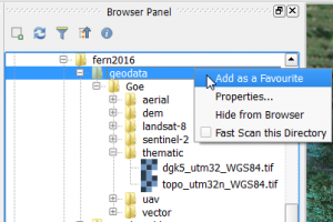
- Right click on the upper part of the main Qgis menu. In the Panel check the box beside the Bowser panel. Drag the Bowser panel window on top of the Layer panel. Browse to your geodata folder where the tutorial data were stored and extracted. Mark geodata and right click Add as a favourite.
 .
.
- In Bowser panel double click on geodata\Goe\thematic\topo_utm32_WGS84.tif to load a topographic map 1:25.000. Load Google maps as background layer. Web --> OpenLayers Plugin --> Google Maps --> Google Satellite. The Project Coordinate system switches automatically to EPSG:3857, WGS 84 / Pseudo Mercator where Enable 'on the fly' CRS transformation is checked. \\ In the Layer panel drag topo_utm32_WGS84 on top of Google Satellite. Double click on topo_utm32_WGS84 to open Layer Properties --> Transparency and change Global transparency to about 70% by moving the slider. Apply.
- Load a raw UAV photo. In Bowser panel double click on geodata\Goe\thematic\DJI00857.JPG. The Coordinate Reference System Selector opens. The UAV photo is a raw image file in JPEG fornmat which does not contain information on a spatial reference system. Just press ESC to load the image. Project Project --> Properties and check Enable 'on the fly' CRS transformation off. Mark DJI00857 in the Layer panel and right click Zoom to Layer. In Layer panel double click on DJI00857 to change the band assignement in Layer properties --> Style to Red band = Band1, Green Band = Band2 and Blue Band = Band3. The raw UAV image is now shown as a true color composite. Striking are the distortions caused by the ultra-wide (fisheye) lens of the UAV camera. [[File:browser_panel.png]
- Load geodata\Goe\thematic\DJI00857_entzerrt.tif in the map viewer where lens distortions were removed using calibration coefficients of a camera model. Open DJI00857_entzerrt.tif in a general image viewer (e.g. MS Windows photo viewer) and rotate the image such that it is correctly oriented to the north direction which facilitates the selection of ground control points. Open Project --> Project Properties , choose EPSG:3857, WGS 84 / Pseudo Mercator and check Enable 'on the fly' CRS transformation on. Mark topo_utm32_WGS84 in the Layer panel, right click Zoom to Layer.

Registration of ground control points (GCP)
- Open the Georeferencer Raster –-> Georeferencer -–> Georeferencer. Open the rotated UAV photo
geodata\Goe\thematic\DJI00857_entzerrt.tif. Define spatial reference system (none) by pressing ESC.
- Change the band assignment to RGB = 1,2,3. Settings --> Raster Properties --> Style. OK.
- Georeferencer --> Settings --> Configure Georeferencer. Check the box beside 'Show IDS' of the ground control points.
- Add ground control points. First, navigate to a ground control point in the UAV image (e.g. drain cover). Zoom in with the magnifying glass or use the mouse roller.
- Zoom in to a point which you can recognize on both the UAV photo and on Google maps in the main Qgis viewer. In the Layer panel switch topo_utm32_WGS84 on and off. Attention: if the zoom factor is too large Google maps is not displayed in the correct position of the main viewer.
- Click on Add point on toolbar.
 .
.
A cross shows up. Move the cursor to the first ground control point (e.g. a drain cover or corner of a building). Zoom in and mark the GCP with the cursor and register the position in the image by a left click. A new window Enter map coordinates opens. Click From map canvas. The Georeferencer window will now minimize automatically.
- Click on the same point in Google maps in the main viewer. The coordinates of the main viewer are now transferred directly to the "Enter map cordinates" window. OK.
Zoom to the next control point, activate add point and continue until at least 10 GCPs are registered.
- For changing the position of a point that is already defined activate Move GCP point.
 . Move the point by clicking on it in the Georeferencer viewer.
- For deleting a GCP activate Move GCP point
 and click on it. Alternatively click on a point in the GCP table, right click delete.
- Save the registered GCP points. File --> Save GCP points as .... Save.
Transformation and Resampling
- Define the transformation settings. Click on

and determine the following settings:

The Target SRS should be the same as the GCP coordinates registered from Google maps: EPSG: 3857, WGS84/ Pseudo Mercator. First, try the transformation type Linear. The horizontal Residuals are now displayed in the last column of the GCP table. In the first column of the table individual points can be switch on or off. Check if the mean error (root mean square error) shown in the grey bar at the bottom of the window can be improved.
- Change the transformation type to Thin Plate Spline. Click on Play
 to create the final georeferenced image file that is loaded into the main Qgis viewer. Compare the results of the two transformation types.
- The SRS EPSG: 3857, WGS84/ Pseudo Mercator does not allow to calculate correct metric distances and areas. Therefore, the georeferenced image needs to be transformed to UTM.
Raster --> Projections --> Warp (Reproject). Determine the following settings:  .
.