Georeferencing of UAV photos
m (→Preparation) |
(→Registration of ground control points (GCP)) |
||
| (23 intermediate revisions by 2 users not shown) | |||
| Line 2: | Line 2: | ||
# Open Qgis with a new project. | # Open Qgis with a new project. | ||
# Prepare main Qgis map viewer: | # Prepare main Qgis map viewer: | ||
| − | * Load a vector file with Ground Control Points (GCPs) that were signalized on ground and measured by a high precision differential GNSS | + | * Load a vector file with Ground Control Points (GCPs) that were signalized on ground and measured by a high precision differential GNSS receiver : {{typed|text=geodata\uas\gcp_points.shp}}. |
Note, the Project Coordinate system switches automatically to '''EPSG:32632 (WGS84 / UTM zone 32N)''' which may be checked on the lower right of the QGIS Map Canvas. | Note, the Project Coordinate system switches automatically to '''EPSG:32632 (WGS84 / UTM zone 32N)''' which may be checked on the lower right of the QGIS Map Canvas. | ||
| − | * Add an aerial ortho photo map as background layer. Open the Datasource manager and establish a connection to a map server: {{mitem|text=Browser --> XYZ Tiles --> Google Satellite}}. | + | * Add an aerial ortho photo map as background layer. Open the Datasource manager [[Image:QGIS_3.0_datasource.png|30px]] and establish a connection to a map server: {{mitem|text=Browser --> XYZ Tiles --> Google Satellite}}. |
| − | * Make sure that the GCP vector file is on top of ''Google Satellite'' in the {{tool|text=Layers panel}} by dragging and | + | * Make sure that the GCP vector file is on top of ''Google Satellite'' in the {{tool|text=Layers panel}} by dragging and dropping the file. |
* Right click on the vector layer name in the {{tool|text=Layers panel}} and {{mitem|text= Zoom to layer}}. | * Right click on the vector layer name in the {{tool|text=Layers panel}} and {{mitem|text= Zoom to layer}}. | ||
| − | * Change the color of the point markers: Right click on Layer name in the {{tool|text=Layers panel}} {{mitem|text= Layer Properties--> | + | * Change the color of the point markers: Right click on Layer name in the {{tool|text=Layers panel}} {{mitem|text= Layer Properties--> Symbology}} |
| − | * Show labels of the GCP layer: {{mitem|text= Layer Properties--> Label}}. | + | * Show labels of the GCP layer: {{mitem|text= Layer Properties--> Label}}. Switch to {{button|text=Single lable}}. Open the '''Value''' dropdown list and select the attribute "Comment". In sub menu '''Text''' you may change font color and font size. |
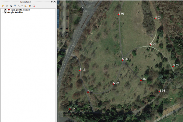
[[File:Qgis_geo_prepare.png|600px]] | [[File:Qgis_geo_prepare.png|600px]] | ||
== Registration of ground control points (GCP) == | == Registration of ground control points (GCP) == | ||
| − | * Open {{mitem|text=Raster –- | + | * Open {{mitem|text=Raster –-> Georeferencer}}. |
| − | * Open a UAV photo that has no spatial reference system (raw image coordinates): | + | * [[Image:QGIS_2.0_addrast.png|20px]] Open a UAV photo that has no spatial reference system (raw image coordinates): {{typed|text=geodata\uas\mavic_ortho_rgb.tif}}. |
| − | * {{mitem|text= | + | * In the Georeferencer window open {{mitem|text=Settings --> Configure Georeferencer}}. Check the box beside '''Show IDs'''. Choose Residual Units: '''Use map units if possible'''. |
| − | * Add ground control points | + | * Add ground control points: First, navigate to a ground control point in the UAV image (e.g. cross signal). Zoom in with the magnifying glass or use the mouse roller. |
* Zoom in to a point which you can recognize on both the UAV photo and on Google maps in the main Qgis viewer. | * Zoom in to a point which you can recognize on both the UAV photo and on Google maps in the main Qgis viewer. | ||
* Click on Add point on toolbar. | * Click on Add point on toolbar. | ||
| Line 23: | Line 23: | ||
{{info|message=Panning without leaving the activated gcp registration | text= Just press the spacebar!}} | {{info|message=Panning without leaving the activated gcp registration | text= Just press the spacebar!}} | ||
Zoom in using the mouse roller, mark the cross center with the cursor, register the position in the image by a left click. A new window ''Enter map coordinates'' opens. Click {{button|text=From map canvas}}. The Georeferencer window will now minimize automatically. | Zoom in using the mouse roller, mark the cross center with the cursor, register the position in the image by a left click. A new window ''Enter map coordinates'' opens. Click {{button|text=From map canvas}}. The Georeferencer window will now minimize automatically. | ||
| − | * Pan and zoom to the same point in Google maps in the main viewer. Left click on the | + | * Pan and zoom to the same point in Google maps in the main viewer. Left click on the point: the coordinates in the Coordinate Reference System of the main viewer are now transferred directly to the "Enter map coordinates" window. {{button|text=OK}}. |
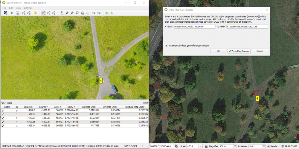
[[File:Qgis_geo_addp.png|1000px]] | [[File:Qgis_geo_addp.png|1000px]] | ||
* Zoom to the next control point, activate {{button|text=Add point}} and continue until 5 GCPs (S01, S02, S03, S04, S06) are registered. | * Zoom to the next control point, activate {{button|text=Add point}} and continue until 5 GCPs (S01, S02, S03, S04, S06) are registered. | ||
| − | * For changing the position of a point that is already defined activate {{button|text=Move | + | * For changing the position of a point that is already defined activate {{button|text=Move point}}. [[File:move_gcp.png]]. Move the point by a permanent left click. |
| − | * For deleting a GCP activate {{button|text= | + | * For deleting a GCP activate {{button|text=Delete point}} [[File:delete_gcp.png]] and click on the point. Alternatively click on a point in the ''GCP table'', right click {{button|text=Remove}}. |
* Save the registered GCP points. {{mitem|text=File --> Save GCP points as ...}}. {{button|text=Save}}. | * Save the registered GCP points. {{mitem|text=File --> Save GCP points as ...}}. {{button|text=Save}}. | ||
| Line 39: | Line 39: | ||
== Quality Check == | == Quality Check == | ||
| − | * Double click on the reprojected layer to open {{mitem|text=Layer Properties --> Transparency}} and change ''Global | + | * Double click on the reprojected layer to open {{mitem|text=Layer Properties --> Transparency}} and change ''Global Opacity'' to about 60% by moving the slider {{button|text=Apply}}. Install the ''Map Swipe tool'' Plugin. This is a tool to make a layer or a group as a curtain above all layers of the map view. It helps checking the geometric quality. |
* Compare the geometry of the reprojected layer with Google maps. | * Compare the geometry of the reprojected layer with Google maps. | ||
* Compare the results of two transformation types ''Helmert'' and ''Thin Plate Spline''. | * Compare the results of two transformation types ''Helmert'' and ''Thin Plate Spline''. | ||
Latest revision as of 21:23, 6 November 2021
Contents |
[edit] Preparation
- Open Qgis with a new project.
- Prepare main Qgis map viewer:
- Load a vector file with Ground Control Points (GCPs) that were signalized on ground and measured by a high precision differential GNSS receiver : geodata\uas\gcp_points.shp.
Note, the Project Coordinate system switches automatically to EPSG:32632 (WGS84 / UTM zone 32N) which may be checked on the lower right of the QGIS Map Canvas.
- Add an aerial ortho photo map as background layer. Open the Datasource manager
 and establish a connection to a map server: Browser --> XYZ Tiles --> Google Satellite.
- Make sure that the GCP vector file is on top of Google Satellite in the Layers panel by dragging and dropping the file.
- Right click on the vector layer name in the Layers panel and Zoom to layer.
- Change the color of the point markers: Right click on Layer name in the Layers panel Layer Properties--> Symbology
- Show labels of the GCP layer: Layer Properties--> Label. Switch to Single lable. Open the Value dropdown list and select the attribute "Comment". In sub menu Text you may change font color and font size.
[edit] Registration of ground control points (GCP)
- Open Raster –-> Georeferencer.
-
 Open a UAV photo that has no spatial reference system (raw image coordinates): geodata\uas\mavic_ortho_rgb.tif.
- In the Georeferencer window open Settings --> Configure Georeferencer. Check the box beside Show IDs. Choose Residual Units: Use map units if possible.
- Add ground control points: First, navigate to a ground control point in the UAV image (e.g. cross signal). Zoom in with the magnifying glass or use the mouse roller.
- Zoom in to a point which you can recognize on both the UAV photo and on Google maps in the main Qgis viewer.
- Click on Add point on toolbar.
 .
A cross shows up. Move the cursor to the first ground control point (cross signal).
Zoom in using the mouse roller, mark the cross center with the cursor, register the position in the image by a left click. A new window Enter map coordinates opens. Click From map canvas. The Georeferencer window will now minimize automatically.
- Pan and zoom to the same point in Google maps in the main viewer. Left click on the point: the coordinates in the Coordinate Reference System of the main viewer are now transferred directly to the "Enter map coordinates" window. OK.
- Zoom to the next control point, activate Add point and continue until 5 GCPs (S01, S02, S03, S04, S06) are registered.
- For changing the position of a point that is already defined activate Move point.
 . Move the point by a permanent left click.
- For deleting a GCP activate Delete point
 and click on the point. Alternatively click on a point in the GCP table, right click Remove.
- Save the registered GCP points. File --> Save GCP points as .... Save.
[edit] Transformation and Resampling
The Target SRS should be the same as the GCP coordinates and the project CRS: EPSG: 32632, WGS84/ UTM Zone 32N. First, try the transformation type Linear. The horizontal Residuals are now displayed in the last column of the GCP table. In the first column of the table individual points can be switch on or off. Check if the mean error (root mean square error) shown in the grey bar at the bottom of the window can be improved. Change the transformation type to Helmert.
- Click on Play
 to create the final georeferenced image file that is loaded into the main Qgis viewer. Compare the results of different transformation types (e.g. Helmert and Thin Plate Spline)
[edit] Quality Check
- Double click on the reprojected layer to open Layer Properties --> Transparency and change Global Opacity to about 60% by moving the slider Apply. Install the Map Swipe tool Plugin. This is a tool to make a layer or a group as a curtain above all layers of the map view. It helps checking the geometric quality.
- Compare the geometry of the reprojected layer with Google maps.
- Compare the results of two transformation types Helmert and Thin Plate Spline.


