SAR flood mapping with SNAP
(→Subsetting) |
(→Visualization of amplitude bands) |
||
| Line 8: | Line 8: | ||
=Visualization of amplitude bands= | =Visualization of amplitude bands= | ||
* Open SNAP Desktop. | * Open SNAP Desktop. | ||
| − | * Drag and drop the zip files of the Sentinel- | + | * Drag and drop the zip files of the Sentinel-1 scenes into the TOC of Product Explorer. |
* Unfold the product folders and Mark the Aplitude_VV bands of both products. | * Unfold the product folders and Mark the Aplitude_VV bands of both products. | ||
* Right click '''Open 2 Image Window'''. | * Right click '''Open 2 Image Window'''. | ||
Revision as of 19:58, 4 December 2019
In this tutorial we will use Level-1 Ground Range Detected (GRD) Sentinel-1 data downloaded from the Copernicus Open Access Hub. The example data is from a study area in Nigeria near the city of Lokoja in Kogi province near the junction of the two large rivers Niger and Benue. During the westafrican monsoon April - September heavy rainfall and floods occur.
Contents |
Data transfer
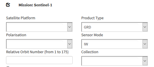
Download example tutorial data from Nigeria or data from your personal region of interest: two Sentinel-1 scenes one pre-event acquisition date and one post-event date: Downloading Sentinel-2 images. Select Product type GRD with VV polarization.
Visualization of amplitude bands
- Open SNAP Desktop.
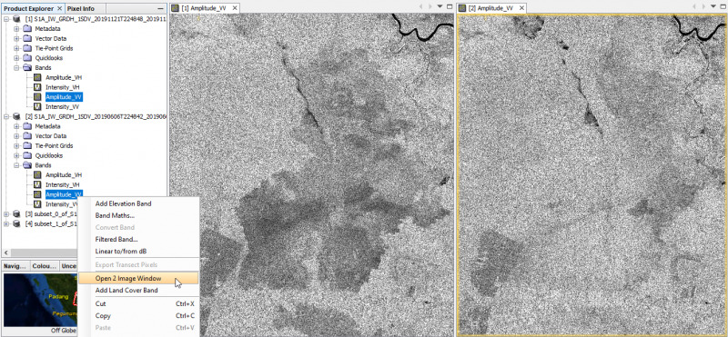
- Drag and drop the zip files of the Sentinel-1 scenes into the TOC of Product Explorer.
- Unfold the product folders and Mark the Aplitude_VV bands of both products.
- Right click Open 2 Image Window.
- Windows --> Tile Horizontally. Both Amplitude bands are shown side by side geometrically linked to each other. The geometry ist still in sensor coordinates in Ascending mode.
Subsetting
Open SNAP Desktop. Drag and drop the zip files of the Sentinel-2 scenes form file Explorer into the TOC of SNAP Product Explorer. We need to reduce the data volume by subsetting the large Sentinel-1 scenes.
- Zoom out to full extent of the S1 scene.
- Activate the Rectangle Drawing Tool

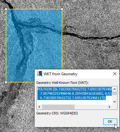
- Left click and drag a rectangular box in the viewer to mark a subset area.
- Activate the selection tool
 and mark the box in the viewer.
- Right click WKT from Geometry.
- Copy the WKT string: CTRL + C.
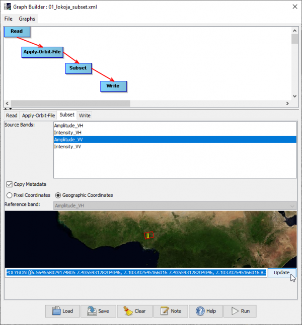
- Open Tools --> GraphBuilder.
- Click Load and browse to the graph file \geodata_lokoja\01_lokoja_subset.xml'
- Click on the Subset tab and activate Geographic Coordinates.
- Paste the WKT string into the text field below the world map: CTRL + V.
- Check if the extent of the subset is displayed correctly onto the world map.
- Click Update to apply the box coordinates.
- Click Save.
- Click the Write tab. Adjust the output directory to you local path.
- Click Run.
- Click the Read tab.
- Choose the second Sentinel-1 source product from the drop down list.
- Click Run.
- File --> Close all products.
- Close the GraphBuilder.
Radiometric and geometric calibration
File --> Open product. Browse to result files from previous work step with prefix Subset_ and extension _Orb.dim.
- Open Tools --> GraphBuilder.
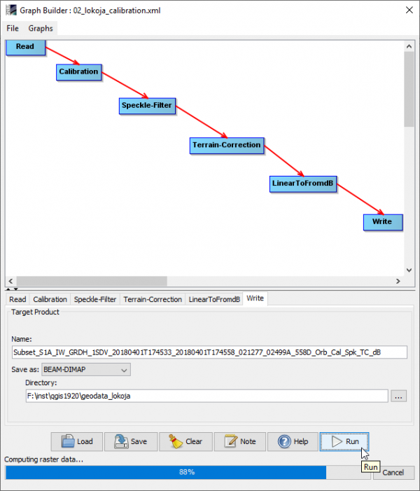
- Click Load and browse to the graph file \geodata_lokoja\02_lokoja_calibration.xml'.
- Click the Write tab. Adjust the output directory to you local path.
- Run.
- Click the Read tab.
- Choose the second Sentinel-1 source product with prefix Subset_ and extension _Orb.
- Click Run.
Change composite
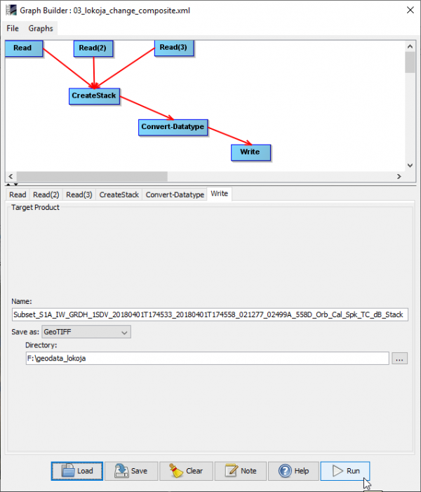
- Click Load and browse to the graph file \geodata_lokoja\03_lokoja_change_composite.xml.
- Click the Write tab. Adjust the output directory to you local path.
- Run.
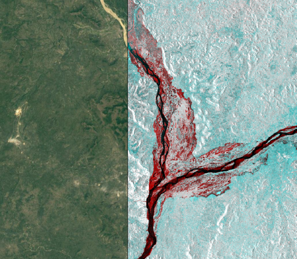
- Open QGIS.
- Data Source Manger --> Browser --> XYZ Tiles --> Google Satellite
- Load the change compoisite file with extension _Stack.tif Data Source Manger --> Raster.
- Adjust opacity of the change layer on top of Google Satellite. Layer Properties --> Transparency --> Global Transparency.
